Fachzeitschrift für Hochfrequenz- und Mikrowellentechnik
RF & Wireless Design KNU
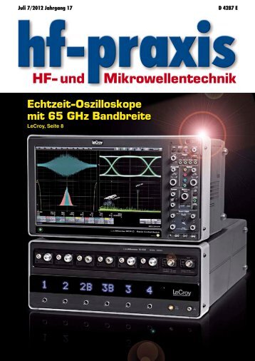
RF & Wireless Design KNU Students Design High-Accuracy AM-FM Radar With Active Reflector Using NI AWR Software Figure 1: Block diagram of the AM-FM radar Company Profile Founded in 1946, Kyungpook National University (KNU) is a national university in South Korea. The Department of Electronic Engineering provides professional engineers focused on advanced research and development in the 21st century and to contribute to industrial competitiveness and national economics. The objective of the EE program is to prepare students for successful careers in a dynamic industry and to meet the needs of an industrial sector for working professionals. The department furthers educational and research capabilities through enhanced cooperation with regional industries and strategic specialization to meet the technological demands of a knowledge-based society. The Design Challenge Accurate non-contact distance measurement systems are widely used in various applications. Position measurement methods depend on the technologies used, including ultrasound, global positioning systems (GPS), laser, and RF/microwave. Each technology has its own advantages and disadvantages. Ultrasonic systems are limited to short-range distances in a small area because of their low precision and are widely employed in rear bumper proximity sensors for commercial vehicles. The accuracy of typical GPS-based distance measuring systems is approximately 10 m, making them unsuitable for the detection of structural faults. Laser sensors have a range of up to several hundred meters and millimeter-level accuracy, however, their performance degrades rapidly under the influence of heavy rain or fog and with lens or reflector contamination. An alignment of the laser beam is also required for accurate measurements. Radar-based sensors using electromagnetic (EM) radiation can operate reliably under harsh weather conditions and are widely used not only in military systems but also in industrial applications such as automotive radars, blind spot monitoring, and level gauges. Research has been done on high-resolution radar technology with the millimeter-level accuracy, where both ultra-wideband (UWB) and wideband frequency-modulated continuous-wave (FMCW) techniques have been used to achieve this level of precision. The student design team at KNU set out to design a practical ranging system with millimeteraccuracy using AM-FM radar combined with active reflectors (Figure 1). The AM-FM radar used narrower bandwidth as compared with other methods and the frequency translating active reflector was used to significantly reduce the phase detection ambiguity in AM radars Figure 2: Fabricated RF front-end modules (a) and (b) and the implemented AM-FM radar (c) and (d) 66 hf-praxis 11/2017
RF & Wireless Table 1: AM-FM radar specifications related to interference or multipath signal reception. The Solution The design team chose NI AWR Design Environment, specifically Microwave Office circuit design software, for this unique, high-accuracy AM-FM radar. The system consisted of two parts, as shown in Figure 1. One part was the base module (BM) AM-FM radar and the other was the tag module (TM) active reflector. In the BM, a 100 MHz oven-controlled crystal oscillator (OCXO) provided the reference signal for the phase detector, as well as the baseband signal of the amplitude modulation. The OCXO was also used as a reference for the phase-locked loop (PLL) in the 10.5 GHz stable local oscillator (STALO) and as a system clock for the direct digital synthesizer (DDS), providing the linear frequency modulation. An amplitude-modulated and frequency-modulated 10.5 GHz signal was transmitted through the TX antenna of the BM and received by the RX antenna of the TM at the target location. The TM converted the center frequency of the received signal from 10.5 GHz to 8.5 GHz with the help of a 19 GHz STALO and retransmitted the filtered and amplified signal using the TX of the TM. Finally, the BM received the 8.5 GHz AM-FM signal and demodulated it into the phase-delayed signal, which was produced by the envelope detector, and also into the beat signal with the help of the frequency mixer. The combination of the phase difference and the beat frequency enabled the calculation of the absolute distance of the target with high accuracy. The overall gain budget was calculated using a spreadsheet and verified using NI AWR Design Environment, specifically Microwave Office circuit design software. Figure 2 shows the fabricated RF front-end modules of the AM-FM radar. For the RF circuit, 20-millimeter thick RO4003 (εr = 3.38; tanδ = 0.0027) substrate was used. Passive components such as the filter, power divider, and power detector were simulated using AXIEM planar EM simulator within NI AWR Design Environment. RF printed circuit boards were mounted in a metal housing in separate channels and regulators for the bias and other circuits were mounted on the bottom side of the housing. The transmit power of the BM was +17.6 dBm. The FM chirp signal was generated using the DDS. With the FM bandwidth of 420 MHz, the chirp period of 200 μs was achieved for both rising and falling. The AM signal was generated using the RF mixer and the combiner. The modulation index was 20 percent. Total RF bandwidth resulted in 620 MHz. The TX spectrum of the BM and the down-converted spectrum of the TM agreed well between simulation and measurement. The IQ mixer and NI DAQ were used for the phase calculation, while the beat frequency was measured with the aid of the NI SCOPE. Detailed system specifications are summarized in Table 1. To verify performance of the proposed system, outdoor experiments were carried out in the University’s parking lot. The measurement results are shown in Figure 3. Why NI AWR Design Environment KNU students chose NI AWR Design Environment for the design of their high-accuracy AM-FM radar distance measuring system because of their familiarity with the software in the classroom, its ease of use, and the robustness of the circuit and EM simulation tools. KNU is a member of the NI AWR Software University Program, which supports teaching universities with NI AWR software donations, enabling students to get a jump start on their careers through experiences with realworld design tools. In addition to the short learning curve, the students were able to simulate the passive components and verify their design quickly with the powerful simulation capabilities in NI AWR Design Environment. ■ National Instruments Ni.com/awr Figure 3: Measurement results of the radar system hf-praxis 11/2017 67