Fachzeitschrift für Hochfrequenz- und Mikrowellentechnik
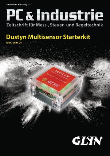
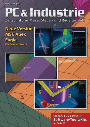
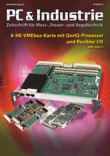
RF & Wireless Figure 11:
RF & Wireless Figure 11: 77 GHz 8 x 8 array single feed network can be specified (Figure 12). This approach enables the design team to investigate the interaction between the beam angle and the input impedance of each individual element, allowing RF front-end component designers to account for impedance loading effects on transceiver performance. This capability highlights the importance of having RF circuit, system, and EM cosimulation to accurately investigate circuit/antenna behavior before fabricating these complex systems. MIMO and Beam-Steering Antenna Technologies For vehicles, a radar will receive unwanted backscatter off the ground and any large stationary objects in the environment, such as the sides of buildings and guardrails. In addition to directpath reflections, there are also multipath reflections between scatterers, which can be used to mitigate the impact of clutter through the use of multipleinput-multiple output (MIMO) antennas. A MIMO radar system uses a system of multiple antennas with each transmit antenna radiating an arbitrary waveform independently of the other transmitting antennas. Each receiving antenna can receive these signals. Due to the different wave forms, the echo signals can be re-assigned to the single transmitter. An antenna field of N transmitters and a field of K receivers mathematically results in a virtual field of K*N elements, resulting in an enlarged virtual aperture that allows the designer to reduce the number of necessary array elements. MIMO radar systems thereby improve spatial resolution and provide a substantially improved immunity to interference. By improving the signalto-noise ratio, the probability of detection of the targets is also increased. VSS software is able to implement user-specified MIMO algo- EM simulators. These simulators not only simulate antenna performance such as near and far-field radiation patterns, input impedance, and surface currents, they also co-simulate directly with VSS software, automatically incorporating the antenna simulation results into the overall radar system analysis without the need to manually export/import data between EM simulator and system design tools. Both AXIEM and Analyst simulators take the user-defined physical attributes of the antenna such as patch width and length, as well as the dielectric properties such as material and substrate height, to produce the electrical response. AXIEM simulator is ideal for patch antenna analysis (Figure 8), whereas Analyst simulator is best suited for 3D structures such as modeling of a coaxial feed structure or finite dielectric (when proximity to the edge of a PCB would impact antenna performance). Figure 9 shows a patch antenna array with corporate feed and 167K unknowns solved in less than 6.5 minutes with a quad core. To determine the physical attributes that will yield the desired electrical response, antenna designers can use the AntSyn antenna synthesis and optimization module. AntSyn software enables users to specify the electrical requirements and physical size constraints of the antenna and the software explores a set of design configurations and determines the optimum structure based on proprietary genetic optimization and EM analysis. The resulting antenna geometry can then be imported in a dedicated planar or 3D EM solver such as AXIEM or Analyst simulators for verification or further analysis/optimization. Planar elements can easily form array structures by combining very simple elements such as microstrip patches. Patches can be configured in a series such as the 1 x 8 patch array in Figure 10, where each element is connected serially by a “tunable” section of transmission line. In this AXIEM project, the lengths and widths of each array element and the connecting transmission lines were defined with variables to allow optimization of the overall array performance. The 1 x 8 array can be further expanded into an 8 x 8 array for a high-gain, fixed-beam design, as shown in Figure 11, replicating the 8 x 8 element array reported in [2]. Within the VSS software, arrays can be represented as system behavioral blocks using the proprietary phased-array model. This enables designers to specify the array configuration (number of elements, element spacing, antenna radiation pattern, impaired elements, gain tapering, and more) for a highlevel understanding of array requirements for desired performance such as gain and side lobes. This approach is best for large-scale arrays (thousands of elements) and system designers developing basic requirements for the antenna array team. The array can also be modeled with the detailed physical array in AXIEM or Analyst simulators. Individual port feeds can be specified or, if the feed network is also implemented in the AXIEM/Analyst simulator, a 64 hf-praxis 12/2018
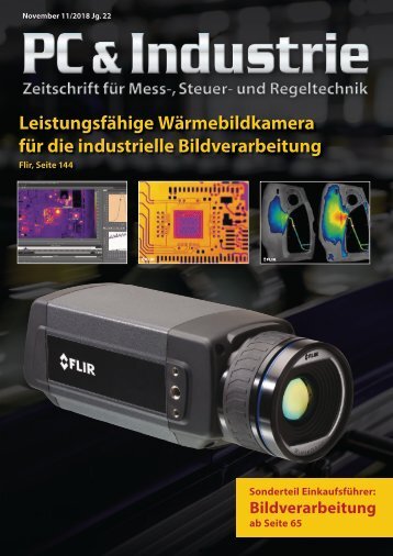
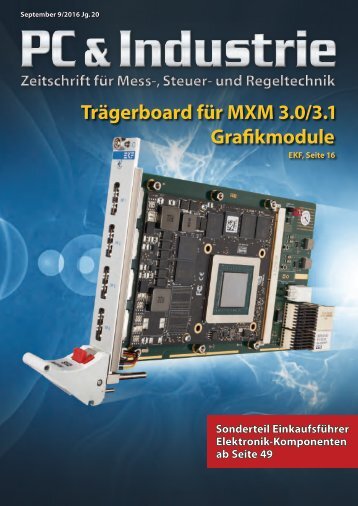
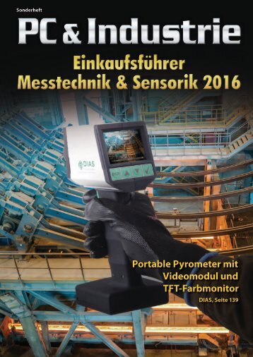
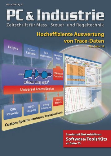
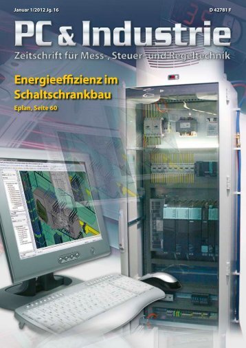
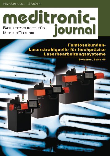
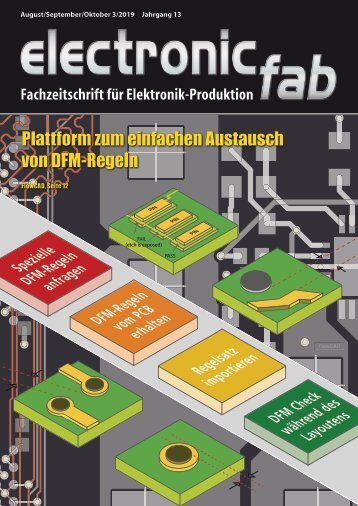
RF & Wireless Figure 12: Simulation of published [2] 8 x 8 patch array on RO4003C PCB, approximately 2.3 x 2.5 cm rithms and evaluate the overall performance as it relates to the channel model, which simulates a highly-customizable multipath fading channel that includes channel path loss, the relative velocity between the transmitter and receiver, and the maximum Doppler spread. Supporting independent or continuous block-to-block operation, the channel can contain multiple paths (LOS, Rayleigh, Ricean, frequency shift) that can be individually configured in terms of their fading types, delays, relative gains, and other applicable features. This module can also simulate a receiver antenna array with user-defined geometry, enabling simulation of single-input-multiple-output (SIMO) systems, as shown in Figure 13. Conclusion This application example has discussed ADAS design challenges and examples have been presented demonstrating how the radar design capabilities within VSS software help designers with overcome these roadblocks. ADAS are becoming more and more prevalent in most vehicles and continued research and development is driving more sophistication and reliability. Advances in simulation technology like the NI AWR Design Environment platform, particularly in RF-aware circuit design, array modeling, and system-level cosimulation, will enable antenna designers and system integrators to optimize these systems for challenging size, cost, and reliability targets. References Rohling, Hermann; Meinecke, Marc-Michael, “Waveform Design Principles for Automotive Radar Systems,” Technical University of Hamburg-Harburg, Harburg, Germany, Proceedings, 2001 CIE International Conference on Radar H. Jeong, H. Y. Yu, J. E. Lee, et. al., “A Multi-Beam and Multi- Range Radar with FMCW and Digital Beam-Forming for Automotive Applications,” Progress in Electromagnetics Research, Vol. 124, 285-299, January 2012 Jri Lee, Yi-An Li, Meng-Hsiung Hung, and Shih-Jou Huang, “A Fully-Integrated 77-GHz FMCW Radar Transceiver in 65-nm CMOS Technology,” IEEE Journal of Solid-State Circuits, Vol. 45, No. 12, December 2010 ◄ Figure 13: VSS software can implement user-specified MIMO/SIMO algorithms hf-praxis 12/2018 65