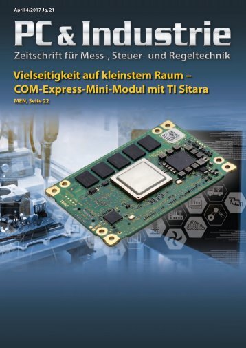
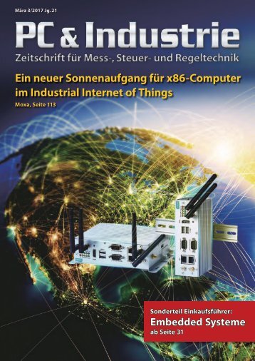
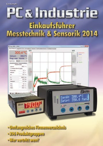
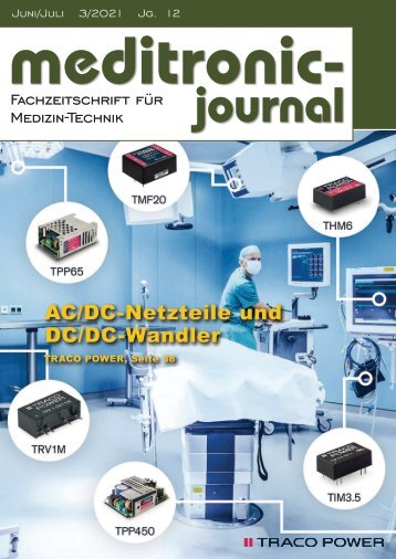
Herzlich Willkommen beim beam-Verlag in Marburg, dem Fachverlag für anspruchsvolle Elektronik-Literatur.
Wir freuen uns, Sie auf unserem ePaper-Kiosk begrüßen zu können.
4-2019
- Text
- Komponenten
- Technik
- Radio
- Filter
- Quarze
- Emv
- Messtechnik
- Bauelemente
- Amplifier
- Wireless
- Antenna
- Oszillatoren
Fachzeitschrift für Hochfrequenz- und Mikrowellentechnik
RF & Wireless In this
RF & Wireless In this example, the feed network is simulated entirely in the circuit simulator. A more realistic example would simulate the layout of the feed network in an EM simulator to make sure the models are accurate and there is no unintended coupling between sections of the network. Figure 5: The Smith chart shows the input impedance to an isolated element and to elements when the entire array is simulated. Load pull contours for power getting to the load are also shown response. The corporate feed network is shown in Figure 2. The power is input from the right side. Wilkinson dividers are used to split the signal and feed the 16 patches. Figure 3 shows the feed for a typical patch. The transmit module and Wilkinson divider are shown in detail on the right side of Figure 3 and the inside of the transmit module on the left side. Each transmit module has a phase shifter, attenuator, and MMIC amplifier chip. The beam is steered by setting the phase and attenuation going into the MMIC amplifier and then sending the resulting signal to the patch. The phase and attenuation are controlled by variables in the software, which can be tuned and optimized as desired. In this manner, the beam can be scanned. Figure 4 shows the 3D view of the MMIC amplifier which is a two-stage, 8-field effect transistor (FET) amplifier designed to work at X-band. Typical circuit simulation results are shown in Figure 5. The system is designed to work at 10 GHz. The purple curve shows the input impedance for an isolated patch from 6 to 14 GHz on a 50 Ohm normalized Smith chart. The marker shows the normalized impedance at 10 GHz. The four crosses show the input impedance of four typical elements at 10 GHz. Note that the interaction between the elements in the array shifts the input impedance of each element from that of an isolated patch. The green contours are load-pull simulations for the MMIC amplifier, showing the power delivered to a load. The shifting of the impedances of the antenna feed results in a 0.5 dB degradation of power to the elements. (Figure 5 power contours are in 0.5 dB increments.) Examples of the antenna pattern are shown in Figure 6. The beam is steered by controlling the relative phasing and attenuation to the various transmit modules. In practice, the harmonic balance takes substantial time to run Figure 6: The beam of the array as it is scanned through typical values of theta and phi 64 hf-praxis 4/2019
RF & Wireless the amplifier and feed network. The load impedances of the array are incorporated into the circuit simulation. This automates the process, saving design time and delivering products to market faster. Figure 7: The antenna pattern is optimized to be below the blue bars with 16 power amplifiers. Therefore, the beam is steered with the amplifiers turned off. The designer then turns on the power amplifiers for specific points of interest. Note: the far-right image in Figure 6 shows a second lobe created when the main lobe is at a near grazing angle. This second example is an 8x8 patch array. Anything that can be tuned in Microwave Office software can also be optimized. For example, in Figure 7, the antenna pattern is optimized for a certain scan angle. In the interests of time, the amplifiers are not included in the optimization. At the end the amplifiers are turned on to see the amount of degradation. The plot is of the total power in the beam, scanning in the theta direction with phi at 0 degrees. The blue bars show the optimizer goals for the measurement. The purple pattern is the original broadside pattern. The optimizer changes the phase and attenuation at the feeds to the patches. The resulting blue curve meets the optimization goal of scanning at 20 degrees with acceptable side lobe levels. Summary Designing antennas with multiple feed points for communications or radar systems requires simulation of the interaction that occurs between the circuit, typically a highly nonlinear power amplifier, the feed network, and the antenna. The beam is steered by the circuitry, and as the beam changes the input impedance or input characteristics of the antenna change, which effects the circuit. The circuit and the antenna are connected, so both must be included in the simulation. The traditional method of simulating antennas with multiple feeds is to simulate the coupled antenna/circuit effects manually using an iterative process that is time consuming and frustrating. Microwave Office circuit and antenna simulation are coupled together, enabling arrays to be easily excited from Conclusion To achieve the aggressive goals of 5G communications, a number of innovations are being pursued, including improvements in OTA efficiency through the expansion of MIMO and beamsteering technologies, both of which will be possible through the development of more complex antenna systems. The strain on design resources for hardware manufacturers will be compounded as more complex antennas must also address the wide range of deployment requirements called for by a densified network of urban-based microcells. This primer has presented some recent advances in phased-array antenna simulation and design capabilities within NI AWR Design Environment platform that will help design teams develop next-generation MIMO and beam-steering antennas for 5G. Try AWR Try NI AWR Design Environment today and see for yourself how easy and effective it is to streamline your design process, improve end product performance, and accelerate time to market for MMICs, RFICs, RF PCBs, microwave modules, antennas, communication systems, radar systems, and more. Download your trial at awrcorp.com/tryawr ◄ Mit einem Klick schnell informiert! • Jetzt NEU: Unser e-paper-Kiosk für noch schnelleren Zugriff auf die aktuellen Hefte • Unsere Fachzeitschriften und Einkaufsführer im Archiv als Download • Aktuelle Produkt-News und ausgewählte Fachartikel aus der Elektronik-Branche • Direkt-Links zu den Herstellern • umfangreiches Fachartikel-Archiv • Optimiert für mobile Endgeräte • Komplettes Archiv der beliebten Kolumne „Das letzte Wort des Herrn B“ aus PC & Industrie Besuchen Sie uns auf: www.beam-verlag.de 65
- Seite 1 und 2:
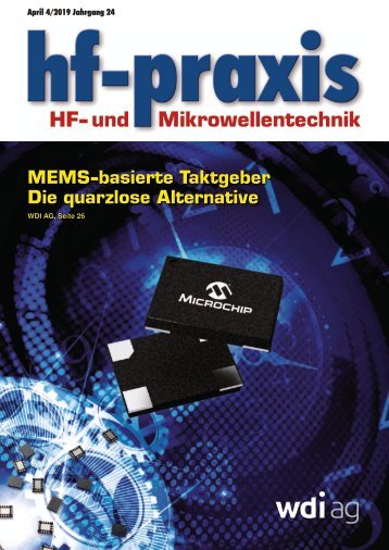
April 4/2019 Jahrgang 24 HF- und Mi
- Seite 3 und 4:
Editorial 50 Jahre Internet Autor:
- Seite 5 und 6:
5G und IoT: 5G: Wundermittel oder U
- Seite 8 und 9:
HF- und Mikrowellentechnik Schwerpu
- Seite 10 und 11:
Quarze und Oszillatoren MEMS-Timing
- Seite 12 und 13:
Quarze und Oszillatoren Neues Evalu
- Seite 14 und 15: Quarze und Oszillatoren Meilenstein
- Seite 16 und 17: Quarze und Oszillatoren Programmier
- Seite 18 und 19: Quarze und Oszillatoren MEMS-Oszill
- Seite 20 und 21: Quarze und Oszillatoren Bild 4: Fre
- Seite 22 und 23: Quarze und Oszillatoren Silizium-ME
- Seite 24 und 25: Quarze und Oszillatoren Ultra-Low C
- Seite 26 und 27: Titelstory Die quarzlose Alternativ
- Seite 28 und 29: Titelstory Bild 4: Aufbau eines MEM
- Seite 30 und 31: HF-Technik Einfach und erschwinglic
- Seite 32 und 33: HF-Technik Bild 2: V OUT /Eingangsl
- Seite 34 und 35: HF-Technik Beispielcode für das Li
- Seite 36 und 37: HF-Technik Das NB-IoT-Signal im LTE
- Seite 38: HF-Technik LTE System Bandwith 3MHz
- Seite 44 und 45: 5G und IoT Was bedeutet es, 5G-fäh
- Seite 46 und 47: Messtechnik Erweiterungen für Sign
- Seite 48 und 49: Messtechnik Schnell, universell sow
- Seite 50 und 51: Messtechnik Eine Einführung: Hohll
- Seite 52 und 53: Messtechnik Gleichung 2 Merkmale m
- Seite 54 und 55: Elektromechanik Hohlleiter-Koax-Ada
- Seite 56 und 57: AWR NI AWR Design Environment Accel
- Seite 58 und 59: AWR Try AWR Try NI AWR software tod
- Seite 60 und 61: Bauelemente Handlicher Spezialschl
- Seite 62 und 63: 5G Primer for MIMO/Phased Array Ant
- Seite 66 und 67: RF & Wireless Distributed Antenna S
- Seite 68 und 69: RF & Wireless Table 1: SunAR’s DA
- Seite 70 und 71: RF & Wireless Matching Network for
- Seite 72 und 73: RF & Wireless 5G Tester contributes
- Seite 74 und 75: RF & Wireless Fully-featured SoC Su
- Seite 76 und 77: MILLIMETER WAVE MMIC PRODUCTS MULTI
- Seite 78: RF & Wireless Record-Breaking Ringa
Unangemessen
Laden...
Magazin per E-Mail verschicken
Laden...
Einbetten
Laden...
hf-praxis
PC & Industrie
meditronic-journal
electronic fab
Haus und Elektronik
Mediadaten
© beam-Verlag Dipl.-Ing. Reinhard Birchel

